Now for the warning: This project contains HIGH VOLTAGE in the 110-120 volt range of AC power. This project has the tendency to be dangerous if not handled with care, precaution, and experience. Please do not attempt this project without an understading of ac/dc theory and safety around such power. I will not be responsible for any damage, injury or death attempted from undertaking my project as displayed on this page. You accept all responsibility if you choose to copy my idea or any part of it.
This project was set forth for the need of a new parking system for my dad's new truck. The one I built the ultrasonic sensor ( Ultrasonic Eyes ) for is the old one. My dad has since then bought an updated version of the same model truck. I would of installed the ultrasonic circuit into that one, unfortunately during un-installing the system from the truck, the board was damaged beyond repair. I needless to say, a very unhappy camper.
Well the first order of buisness was to decide if I wanted to take the money and the time to build another mobile parking device for the truck. Since I didn't have either, I decided to build a static device for just parking the truck into the garage, as it's hard enough fitting the truck in the garage and leave ample space as is.
The first thing I thought of is to build a sensor of some sort to sense the trucks position dynamiclly. I thought about this, and decided that it would take to much time to work out a solution for it, plus it would be prone to problems. So i then decided to go with static sensor solution. The next order of buisness would be to figure out how to activate the circuit on a timer so that the ciruit would not always be on, plus i needed a way to activate the timer when neeeded.
The first solution I thought of was to use a 555 timer to time the on/off time of the ciruit. But activation was still a problem. While I was looking over the problem I was playing with the garage door and then a lightbulb came on over my head. NO REALLY, it actually did, in form of the garage door motor courtesy light. Yea, yea, i know bad interlude to a joke. But hey, I thought it was funny. The light always turns on when it is being used to pull a vehicle into the space. Plus it always turns off after a given time.
With that as a solution, all I had to do was figure out a way to use this available timing source. I decided to use an AC relay. The next thing was to design the sensor circuit. This is what I came up with:

Yes, I know by far thats not how you design a schematic, but who cares....I Don't, so please, no e-mails about my schematic, you can kiss my ass if you dont like it!!! <deep breaths shadow>. Ok, much better now that I got that out of the way.
As you can see in the schematic, when the circuit is activated, a green led shows that the circuit is activating for added insurance. The red led comes on only when the pressure switch is activated.
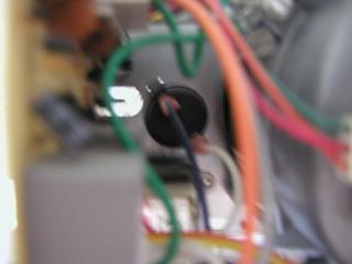
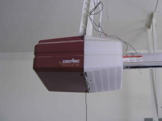
Next, i needed to get started on setting up the relay to the light bulbs. So here is what I found inside of the garage door motor unit:
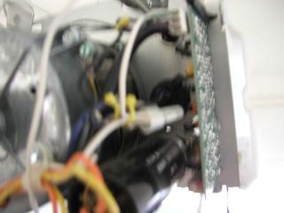
And here is what it looked like when I spliced it:
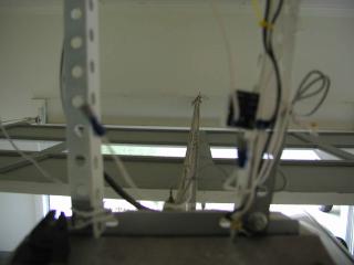
I was forced to use wire terminal clips on the ends of both wires to hook up to the light bulb and the AC relay. I bought the relay at Radio Crap (You've got questions, the hell if we know how to answer them) and installed it on the supporting rack with wire tie, and epoxy glue for added strength:
Once the relay had been wired up with the AC relay input, the next order of buisness was to run the DC switch wires on the ceiling and down the wall to the ciruit. After that I went on to finally sit down and build the actual sensor circuit.
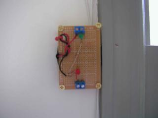
This is what I came up with:
Once that was completed and mounted on the wall, I was ready for testing. Unfortunately I had to change out the green led for a red led since the green led was was partially broken. Oh well, it still works just as well with a red led, its just not green.
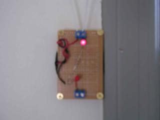
This is what it looks like when the garage door courtesy light is on:
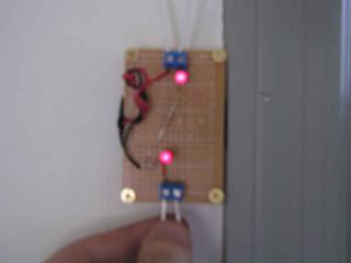
And this is what it looks like when the pressure sensor is tripped:
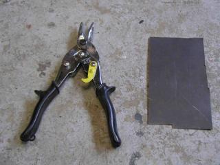
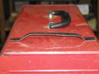
The next part of my project was to create some sort of home-made sensor that could with stand repeated abuse from the weight of vehicles on it over a long period of time. The idea I came up with is to use a metal slat over a screw to make a switch. I have some spare metal slats in a box I decided to go through and found the perfect piece. Here is what I found and the tool to cut it with:
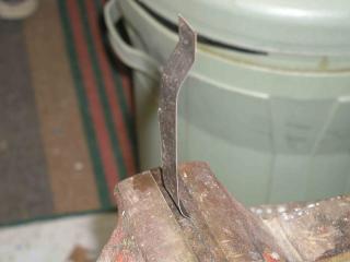
Next, I cut out a long piece of the metal and formed it to create a rasied platfrom of the metal:
And this is what it looked like when formed:
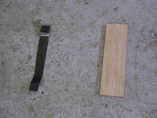
Then I found a piece of wood and cut it to size for the metal. Here is what that looked like:
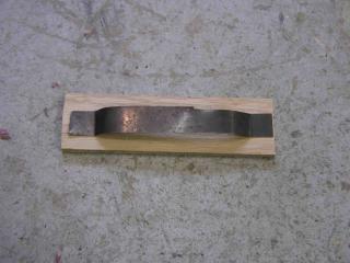
And the metal on top of the wood:
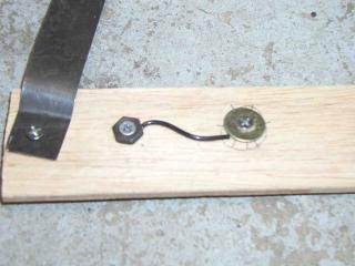
Next, I cut holes in the wood, and connected it the wood and wired up the screw bottom sensor button:
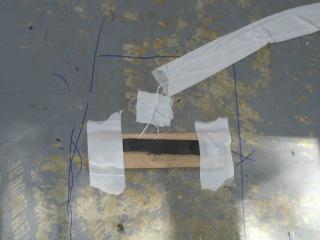
After the pressure sensor switch was built, I got dad to position the truck where he wanted it in the garage, and marked out the position the front right tire (tire closest to the wall) was in by outlining it with a sharpie. Then i placed the sensor in position and wired it to the sensor wires that go to the circuit and taped down everything:
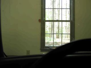
Next, I got the truck ready for a test run. Worked beatifully. Here is what it looks like from inside the truck, you can just make out the circuit in the pic next to the window:
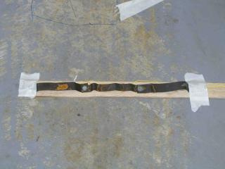
The only redesign I have done since then, was to build a three long sensor to make sure that in any approach to park, the sensor is tripped:
